

*These steps should be taken after ruling out a gateway issue, see "Troubleshooting Cell and Solar Gateway Connectivity" and “Gateway Lights.”
Definitions:
- Gross Weight: A sensor’s gross weight displays the total weight that is being detected on the top of the scale before the container weight is subtracted from it.
- Container Weight: A sensor’s container weight should be the weight of the tank/container when it is empty. Gross weight - Container weight = pounds of product currently in tank. The container weight set will affect the reading in pounds and the percentage.
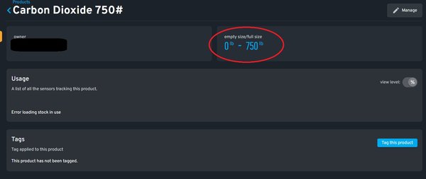
- Product Empty Size: The amount entered for the product that is considered empty, usually zero. This sets the 0% mark in the graph. This will only affect the percentage remaining.
- Product Full Size: Should be set to the weight of the contents when full. This sets the 100% mark on the graph. This will only affect the percentage remaining.
- Junction Box: A blue square plastic housing inside of the scale which houses a circuit board and where all the scale's wires route to.
Tools Needed:
- PH2 or PH3 Screwdriver
- 1/8'' Flathead screwdriver
- Needle-nose Pliers
- Wire strippers
- Power Drill or Long Allen Wrench/Allen Wrench and Mallet
- A Gateway that is set up and working
Step 1: Viewing and Verifying the Gross Measurement, the Container Weight, and Product
Viewing and Verifying the Gross measurement
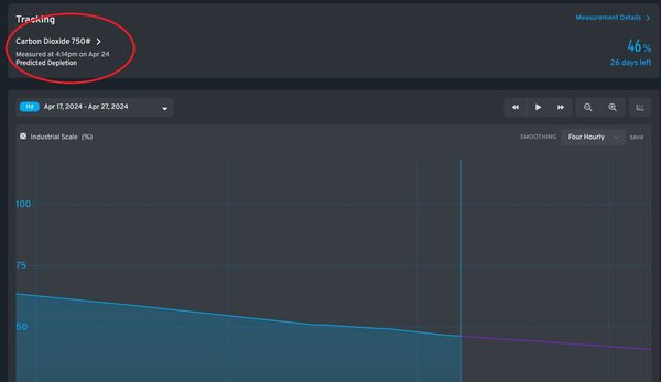
- Naviagte to the sensor page and locate the measurement detials section: This will be located in the top right next to the product name. (The measurement details may not be available if the sensor has not been seen in a long time).
- Verify that the gross weight and container weight seem to be accurate.
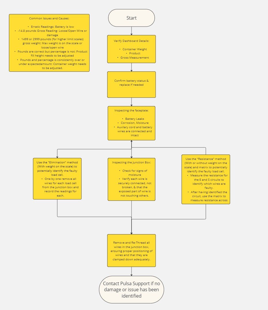
- The lowest a scale will read for gross weight is -14.8 pounds. This is considered a scale's “true zero”, as it is the lowest a scale can possibly read. A gross measurement reading of -14.8lbs may signify that there is a hardware issue present, such as a wiring issue inside of the junction box or damage to the circuit board, or to the load cells from overloading.
- A scale’s max safe overload is 4000 pounds of gross weight if weight is dropped in the middle and 2000 if the weight is accidentally placed is dropped in a corner
- Ensure that the feet are installed on the scale: Push diagnol sides of the scale with your fingers to ensure that the scale is evenly balanced on the ground and adjust the feet if needed.


Verifying the Container Weight
- Ensure that the contianer weight set is accurate: Some tank manufacturers list the empty weight on the tanks, and for others you may need to research on the tank manufacturers site or call their support line to get the tank’s empty container weight. Another option is to weigh the container on a scale when it is empty.
- A scale reading that is higher than expected can indicate that the actual/true container weight is higher than the container weight that was entered. If you believe this to be the case, you should adjust the container weight to be higher according to the container weight’s true weight.
- Any additional hardware/ items placed or installed atop the scale should be taken into consideration when determining container weight, as any added weight to the container/tank that is unaccounted for in the container weight will cause the sensor to read higher than expected.
- A scale reading lower than expected can indicate that the actual container weight is lower than the container weight that was entered. If you believe this to be the case, you should adjust the container weight to be lower according to the container weight’s true weight.
Viewing and Verifying the Product details
- Verify the product specifications: Navigate to the product details page by clicking/selecting the name of the product on the sensor page.
- The product’s full size associated with a sensor should be set to the weight of the contents when full. The sensor's percentage may be reading lower than expected if the product's actual full size is higher than what it was set to in the product set up. If you believe this to be the case, you should adjust the product full size to be higher on the dashboard.
- The sensor’s percentage may be reading higher than expected if the product’s actual full size is lower than what it was set to in the product set up. If you believe this to be true, you should adjust the product fill height to be lower on the dashboard
- Also ensure to verify that any conversions are accurate on this screen.
If changes were made during this step, we can check on the accuracy of the scale by pressing the orange button on the front of the scale to force an immediate pulse from the sensor. Otherwise, move on to Step 2.
Step 2: Confirming the battery status and replacing if needed
Signs of a Low Battery
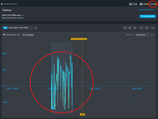
- Signs of a low battery include periods of missed readings, and dips in readings.
- A low battery can be identified on the trend graph due to the overall shape of the graph when zoomed out seeming accurate, but noticeable dips within that time period.
- The low battery flag on the upper right corner can also help to identify that a battery is low. (Please note: The low battery feature is less reliable on scales version 1, as this feature was made available after the creation of these scales. This means that if you have an older scale that is not version _002 and above, you should still check the battery even though the battery flag is not marked low).
- Ensure that the correct battery type is being used. Link here for sensor batteries.
- You can check a battery’s voltage with a battery checker or multimeter to verify if the voltage of the battery is 3.6 volts.
After replacing the battery,, we can check on the accuracy of the scale by pressing the orange button on the front of the scale to force an immediate pulse from the sensor. Otherwise, move on to Step 3.
Step 3: Inspecting the Faceplate Electronics
Remove the faceplate
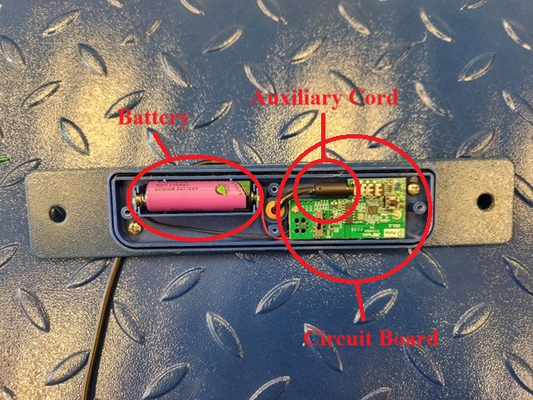
When replacing the battery, the faceplate electronics will also be visible. With a screwdriver, remove the 2 smaller screws on each side to rveal the battery and circuit board.
Check for signs of damage on the board and battery leaks:
- White, blue, or yellow powder-like substance
- Smell similar to that of a rotten egg and fluid that can be observed around the battery site.
- Lighter-Colored or raised/wrinkled areas on the PCB board
- Debris and dirt (Which can corrode a board and cause it to degenerate over time)
- Droplets of water/moisture
This is also a good time to ensure that the auxiliary cord is securely connected to the faceplate’s PCB Board. At times the cord that connects from the inside of the scale to the faceplate may become disconnected. Re-connecting the auxiliary cord might require some slack to be obtained from the wire.
Next, we should remove the faceplate from the scale completely to inspect the wiring for damage.:
- We can remove the faceplate completely by removing the 2 larger screws on the side of the faceplate with a phillips screwdriver.
- Pull the faceplate out as much as possible without excessive tugging to reveal the wiring that connects to the load cells inside of the scale and inspect it for damage. (Our industrial scales feature rat guards, but some smaller rodents may still be able to get through to chew on the wire.)
- A common sign of damage to the wiring will be erratic and negative readings on the graph, including a -14.8 gross measurement in the measurement details.
Step 4: Inspecting the Junction Box
Reveal and Inspect the Scales Junction Box
- After having removed the faceplate and pulling out the wiring, you will notice a blue box where all of the wires route to. This is known as the "Junction Box."
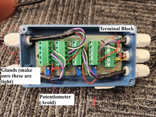
- Open up the junction box with a screwdriver and this will reveal the interior of the junction box, which comprises the terminal blocks, wires, and potentiometers.
- Inspect the junction box for signs of damage and moisture. Although more rare than moisture in a faceplate, it is possible that moisture could collect here due to flooding.
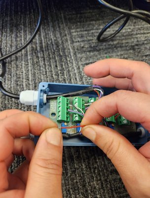
- You can use a small flathead screwdriver to gently tug each wire. The wire should be secure and should clamp down on the wire itself, and not on the colored heat shrink that covers the wires.
- There may be times when an issue is caused by the wire being clamped down so hard that it is essentially broken inside the clamp. There are other times when the wire may be broken in the colored shrink wrap. To ensure this is not the case, use your hands or needle nose pliers to tug on the ends. If there is a break in the wire you will feel the wire sliding out of the shrink wrap.
- If a wire has been cut, or you need to reveal more wire to re-connect it and clamp it down, use wire strippers to reveal about ¼” of wire.
- Remove every single wire going into each terminal block using the flathead screwdriver. Re-insert and re-tighten the clamps with the small flathead screwdriver. Be sure to make note that when re-inserting the wires that the position of the colored wires matter. You can take a picture of the color sequence before removing the wires to note the positions of the E+, E-, S+, S-, and Ground wires. This will help you make sure that you are placing them back in the same order as before. Also note to make sure that each wire is securely clamped down, and that the clamp is making contact with the wire itself and not the colored shrink wrap.
- *** Be sure to avoid adjusting the potentiometers on the bottom of each terminal block as these are used to balance the scale and should be avoided. *** Also ensure that the Glands are tight as these prevent moisture from entering the junction box.
- ***Make sure that the bare portion of the wire is not making contact with any other wire. This will produce inaccurate readings.***
If changes were made during this step, we can check on the accuracy of the scale by pressing on the button on the right of the PCB board to force a pulse from the sensor.
Step 5: Inspecting the rest of the wire for damage
Inspecting the Wire near the Load Cells for Damage
The last step to take in troubleshooting an industrial scale would be to inspect the remainder of the wire, which is rolled up inside of the scale and not accessible by pulling out the faceplate and junction box. For this step, all weight placed on the scale should be removed and the scale should be placed upside down.
(There is also an alternative method where a specific load cell or wire can be identified as having probable damage without having to remove weight from the scale, discussed below).
- Use a power drill with the appropriate attachment, or alternatively an allen wrench with a mallet to loosen up the screws on each corner of the scale.
- Remove the rat guards and set aside along with the screws. The scale's 4 load cells will become visible, as well as the remainder of the wire for each one.
- Inspect the remainder of the wire for signs of damage like chewing or visible nicks. This would cause the scale to read very erratically, negative, and very commonly a gross measurement minimum of-14.8 or max measurement of 1499 or 2999.
- After inspecting the rest of the wire, we should assemble the scale back together in its entirety, and can confirm measurements by pressing on the button on the right of the PCB board to force a pulse from the sensor.
***Alternative Methods:
If you cannot remove the weight from the top of the scale, it is sometimes possible to identify which specific wire or load cell is damaged via the following steps:
Elimination Method:
- One by one, go through each terminal block and disconnect all wires for just that terminal block. (You should need to do this for the terminal block that connects to the faceplate, since the wire in its entirety is visible once you have removed the faceplate). Press the button on the face plate to get an instant reading, and make written note of the measurement.
- Continue to do this for each terminal block.
- After having completed this for all four terminal blocks, you might realize that one of the terminal blocks when disconnected produced a different reading than the rest, and might have fixed or made the reading alightly more accurate.
- This means that you have found the load cell and wire group that may have been damaged.
- This method is limited since you may get a different outcome if more than one load cell and wire group has experienced damage. You will still need to at some point remove the weight from the scale in order to turn the scale upside down to open up the scale and visually confirm damage, but can be useful so that you only need to open up one side.
Resistance Method:
(For this method you will need a multimeter that is calibrated to read resistance in hundreds).
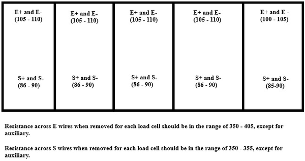
- Using the markers on the sides of the junction box to identify each wire, measure the resistance across each positive and negative wire for each load cell and match it to the matrix.
- ***Make sure to disconnect ALL the wires from the load cell before measuring the resistance of the E and S wires.
- If u get something vastly different than the ranges on the matrix, this will indicate wether the issue lies in the E wires, S wires, or both. However, we will need to do the following step to identify the particular load cell.
- After having identified wether the issue is in an E or S wire, go through and unplug all the wires for each terminal block one by one. Then, measure the resistance for the positive and negative wire and match it to the matrix.
- Any resistance measurement that varies drastically from the range on the matrix wil reveal the specific load cell that is the issue.
These methods will reveal which load cell is faulty, but at some point you will still need to open up the scale to verify any if there is any damage in the interior of the scale.
Step 6: Contact Support
After going through these steps, iIf you are unable to identify the issue causing your scale to malfunction, please contact Pulsa Support at:
(916) 579-7267
support@pulsasnsors.com
(We recommend taking pictures of the scale, faceplate, and junction box during troubleshooting to ensure a smooth and speedy support request).